Saturday 10 December 2011

'Opening Night' Showreel

Here's a short Showreel for 'Opening Night' that sums up a lot of the work we've done so far. Enjoy.

OPENING NIGHT Showreel from Joshua Flynn on Vimeo.

Josh has written a more detailed post about our Showreel so hop over to his blog to learn more.
Joshua Flynn Blog

That's all for now. More in the New Year.
Happy Holidays.

Tuesday 15 November 2011

Ball & Socket Armatures - Finished

      After several weeks of work I've finally finished making my new ball and socket armatures. My plan is to replace the aluminium wire armatures that are currently in my 'Roy' and 'Elle' puppets. This should make them more resilient and professional. You can read about my aluminium wire armatures HERE.
The two armatures featured below follow identical designs but have different proportions to suit the male and female characters. I've wanted to make  full ball and socket armatures for a long time and I really pleased with how these turned out. I got a little trigger happy with my camera so expect lots of pictures.

'Roy' Male Ball & Socket Armature

First of all we have Roy's new armature. He's build from a mixture of steel and K&S square brass tubing. It has 24 points of articulation that are controlled by 17 screws around the body for tension adjustments.

He has a double ball and socket waist and sing ball jointed head, neck, shoulders, arms, hips, legs and ankles. His elbows, knees and toes and hinge joints.

       I tried to position the figure in interesting, dynamic poses but by the time I got to that last picture my creativity fizzled and I went for the cheesy 'whats that in the distance' pose. I kind of like it, plus his white hands make him look like a really skinny mime artist.
The puppet wasn't tied down to the floor for these pictures. He's just balancing by himself. The feet have a M3 nuts in the toe to allow the character to be bolted to the set. Just like in my wire armatures the K&S allows the puppet to be disassembled. The feet and hands slide off for maintenance and repairs. The hands are made from aluminium wire with a Milliput palm. You can read about how I make puppet hands HERE.

The turn around picture above shows the armature from various angles. click the image to embiggen!

'Elle' Female Ball & Socket Armature

Now we move on to the female armature for 'Elle'. This was more challenging to make due to her slender physique. The hinge joints for the elbows and knees are made from a thinner steel to save as much space as possible.
I tried to pose the armature to give it a more feminine vibe. If ,like my brother Josh, you find yourself thinking  'thats one sexy lookin armature' then I think you need to get out more.
Both armatures have K&S tubing soldered onto the hips. These act as rig points just in case the puppet needs external support. ( For example if a character is jumping or running and needs to be held off the ground.)
The biggest difference in this armature is the feet. 'Elle' wears high heels and her feet are much smaller than 'Roy's'. Its always very challenging building things to be smaller. To get around this problem I made a new ankle joint that wound fit inside her small feet. Because she's wearing heels there's no toe joint but there is an M3 nut for tie downs.
In the picture above I was going for a casual sitting down look, rather than 'I hurt my knee'. You be the judge.
Just like before, click the image to embiggen this cromulent turnaround picture!
Comparison Shots

Finally he's some comparison shots so you can see the differences between the two armatures.


Below I photographed them standing next to the wire puppets. Hopefully this shows how they fit inside the characters. My next stage is to start bulking out the armatures with foam and casting them inside new silicone limbs to make 'Roy & Elle Mark II'


That's all for today. Hope you found this post interesting.
Stay tuned for more developments.

Nathan.

Sunday 6 November 2011

Ball & Socket Armature - Hinge Joint

Hinge Joints

In today's post I'll continue discussing the construction of my Ball & Socket Stop Motion armature. I'll be showing how to make a different kind of joint called a Hinge Joint.
Hinge joints don't offer as much movement as Ball and socket joints, but they're perfect for creating elbow and knee articulation. Plus they're much simpler to make.

I'm making my hinge joints from steel bar. The materials and tools needed are similar to those used to make ball and socket joints. You can see/read about that in my previous post. LINK

I start by cutting 3equal lengths of steel bar. Above you can see the steel bars along with the M2 nuts and bolts that will be used to hold them together.

Next I marked a dot on the steel about 4mm from the end. This is where the hole will be drilled for the bolt. Before drilling I made a centre punch on the surface to guide the drill bit.

I stacked and clamped the 3 bars together and held them in a vice while drilling. I started with a M1.5 drill bit and then expanded the hole to M2.

This gave me 3 identical steel bars, all with an 2mm hole drilled in one end.


I used a M2 nut and bolt to tie all the bars together. I then rounded the corners (seen above in the picture on the right).  To do this I used a rotary tool and a reinforced cutting disk. (the same technique I used for making ball and socket plates in my last post.)

Next I loosened the bolts and rotated the middle bar so it was pointing in the opposite direction. I'm using K&S brass tubing to make my arms and legs so I cut the steel bar small enough to slot inside. This will be soldered together later.

I cut another small square of steel bar to go on the other end of the joint. This will be used to hold the two outer bars together and act as a tab to slot more K&S onto. I used a file to rough up the surfaces where each part will connected and applied soldering flux.

The rough surfaces help solder stick. Its also important to remove any dirt or grease to create a stronger join. I heated up the steel using my butane torch until the flux paste fizzed and then applied silver solder to the both side of the tab.

At this point I also soldered the nut onto the outer surface. This allows the joint to be loosened or tightened using just an Allen key. Above you can see the joint after being soldered.

The other end now needs to be cut smaller to allow it to slot onto the K&S. Also to give the joint a little more range of movement I marked where more steel can be removed. To do this I use the rotary tool and cutting disk.

Here is the joint after cutting. The change is only small but this allows the joint to bend into a smaller, acute angle. For example, If this joint was to be used as a elbow the character would now be able to touch their own shoulder. Or if this was a knee joint, the character could crouch down lower.

The final stage is to slot the joint into the K&S tubing and solder the join.

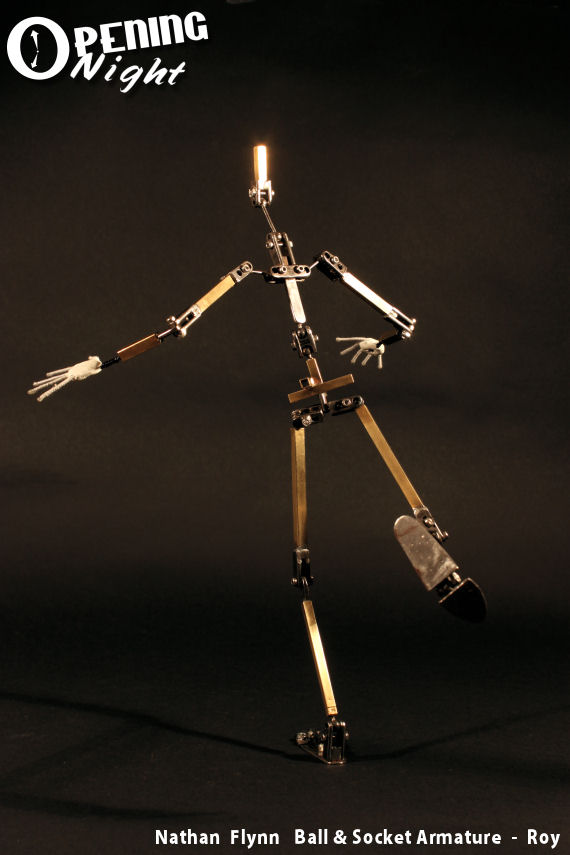
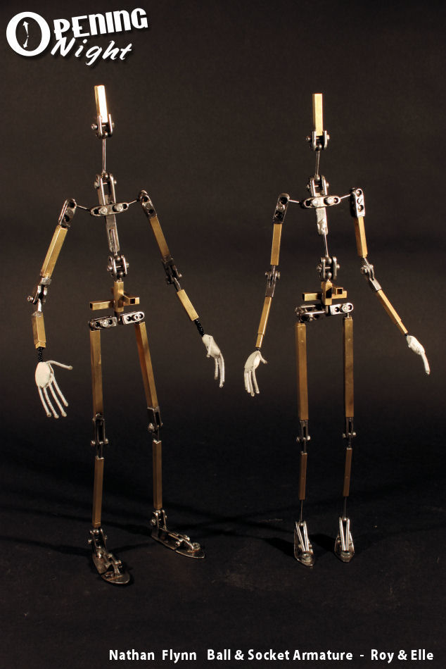
Wallah ! One hinge joint ready to be incorporated into a character armature. I will be using the one pictured above as a knee joint for my new 'Roy' (Mail Man) armature. I'm also using this kind of joint to make his elbows and toe joints. 'Elle's' knees and elbows will be made smaller with thinner steel bars.
The excess bolt will be cut shorter later. I usually leave them on until I'm done.

Thanks for reading.